SpoolEase Duo Build Guide
SpoolEase Duo is a new build, so these instructions may contain inaccuracies. Please read them carefully, and if anything is unclear, ask on GitHub or Discord.
SpoolEase Duo combines the Console and Scale in a single device. Like the Console, it also supports an additional remote standalone Scale. It is an alternative to the console and cannot cooperate with another Console.
This guide provides step-by-step instructions for connecting the WT32-SC01-Plus board to a PN532 NFC module, and an HX711 and a load cell.
Once wiring is done, print the 3D model of the case and fit the components into their locations, use screws wherever required and close the case. Make sure that the wiring doesn't interfere with NFC reception, the load cell or the top plate.
Once you complete, build is done.
The 3D model 3mf file on MakerWorld includes two cases. One with cable entry on the left and NFC scanning on the right, and another with cable entry on the right and NFC scanning on the left. Assembly instructions below are based on the first one, so mounting of all parts differ a bit on the latter case. Also, for the latter model to display properly and not upside down need to configure the orientation in the device display settings configuration.
Connector Placement
The WT32-SC01-Plus has two connectors:
- A 7-pin connector for the HX711
- An 8-pin connector for the PN532
PN532 Wire Preparation
The 8-wire cable has connectors on both ends. Since the PN532 module requires soldering, follow these steps:
- Cut off one connector from the 8-wire cable.
- Strip the insulation from the first 7 wires to expose the wire ends for soldering. Leave the eighth wire insulated and unconnected.
Wiring Instructions
IMPORTANT: The wiring follows the pin number on the display and the signal name on the PN532. Some devices may come with wire colors in a different order (e.g., sometimes 🟩 green and 🟨 yellow reversed in the received wires). Always connect by pin number and signal name, not by wire color.
| Wire # | Color | WT32-SC01-Plus Pin | PN532 Connection |
|---|---|---|---|
| 1 | 🟥 Red | + | VCC |
| 2 | ⬛ Black | - | GND |
| 3 | 🟩 Green | SS | |
| 4 | 🟨 Yellow | MOSI | |
| 5 | 🟦 Blue | MISO | |
| 6 | ⚪ White | SCK | |
| 7 | 🟧 Orange | IRQ |
Configuring the PN532
IMPORTANT: Many users don't notice this step. Make sure you do it now !
The PN532 has two small dip switches that must be set to SPI mode. With the board oriented so that the dip switches are at the bottom right, set the left switch down and the right switch up.
Tips/Recommendations
- Solder the wires to pass on the opposite side of the antenna to prevent interference with NFC reception. The antenna is the thick white line around the board (note that the photo does not follow this guideline).
- Keep the wires to the necessary length. Consider the required length to assemble everything (including the ability to remove the display with the PN532 inside), how to route them within the case to avoid interfering with the WiFi antenna, and other factors. Excessively long wires can cause electrical interference.
Reference Image
The following image shows the PN532 wiring for the Console. For the Duo, use an 8-wire cable in the 8-pin connector and leave the eighth wire unconnected.

HX711 and Load Cell Wiring
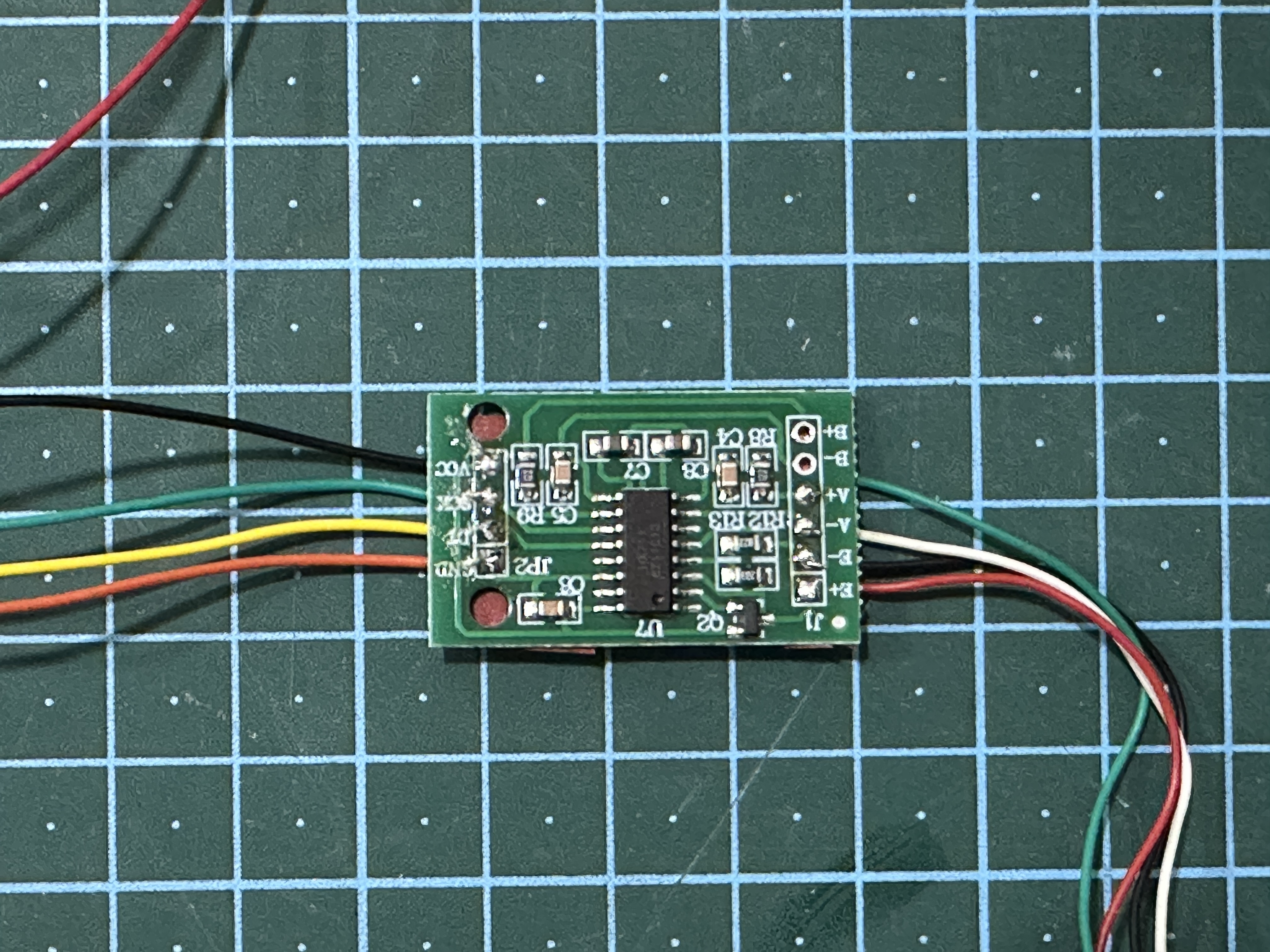
The HX711 PCB has connection points on both sides:
- One side has 4 holes for WT32-SC01-Plus connections
- The other side has 6 holes (only 4 used) for load cell connections
Begin by soldering the WT32-SC01-Plus side connections (all 4 holes need to be wired).
For the load cell side, precise wiring is critical.
A helpful technique: insert wires through the holes, secure with masking tape, then solder from the opposite side.
Load Cell to HX711 Connection
| Load Cell Wire Color | HX711 Pin |
|---|---|
| 🟥 Red | E+ |
| ⬛ Black | E- |
| ⚪ White | A- |
| 🟩 Green | A+ |
Soldering technique

hx711 fully soldered
Connect HX711 to WT32-SC01-Plus
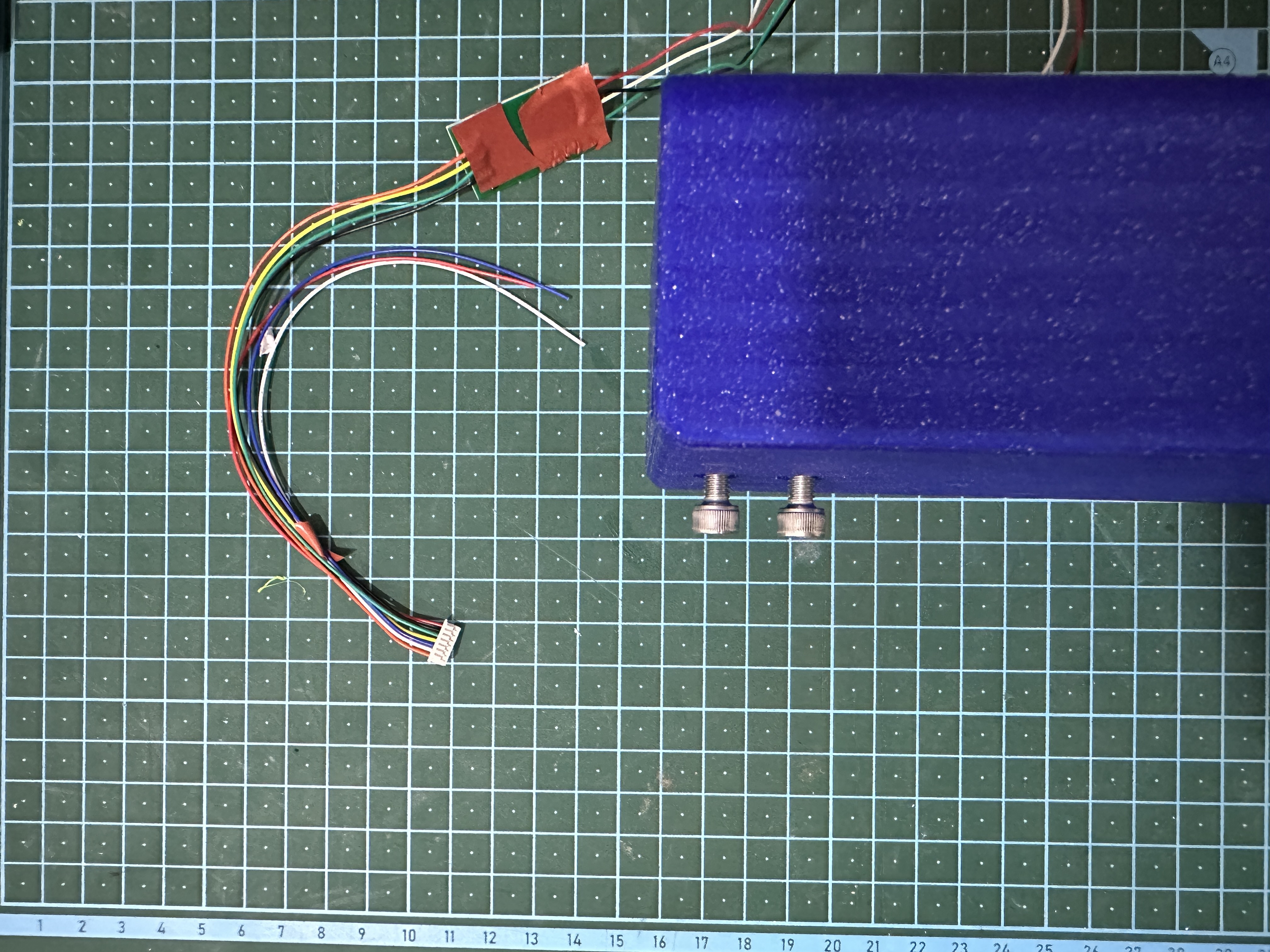
Connect the HX711 to the 7-pin connector on the WT32-SC01-Plus using the 7-wire cable supplied with the board and the following pin mapping. The PN532 remains connected to the 8-pin connector. Leave the unused wires insulated and unconnected.
The pins are numbered from 1 to 7. Pin 1 is closest to the 8-pin connector, under the DE of the DEBUG label. Pin 7 is near the 2-pin connector marked SPK, under the small push-button on the board.
If you use the 7-wire cable supplied with the board and want to reference the colors in the table below, verify first that the colors on the cable are in the following order: Red, Black, Green, Yellow, Blue, White, Orange.
| HX711 Pin | WT32-SC01-Plus 7-Pin Connector | Original WT32-SC01-Plus 7 wires connector color |
|---|---|---|
| VCC | Pin 2 | ⬛ Black |
| SCK | Pin 3 | 🟩 Green |
| DT | Pin 4 | 🟨 Yellow |
| GND | Pin 7 | 🟧 Orange |
Mount the Load Cell
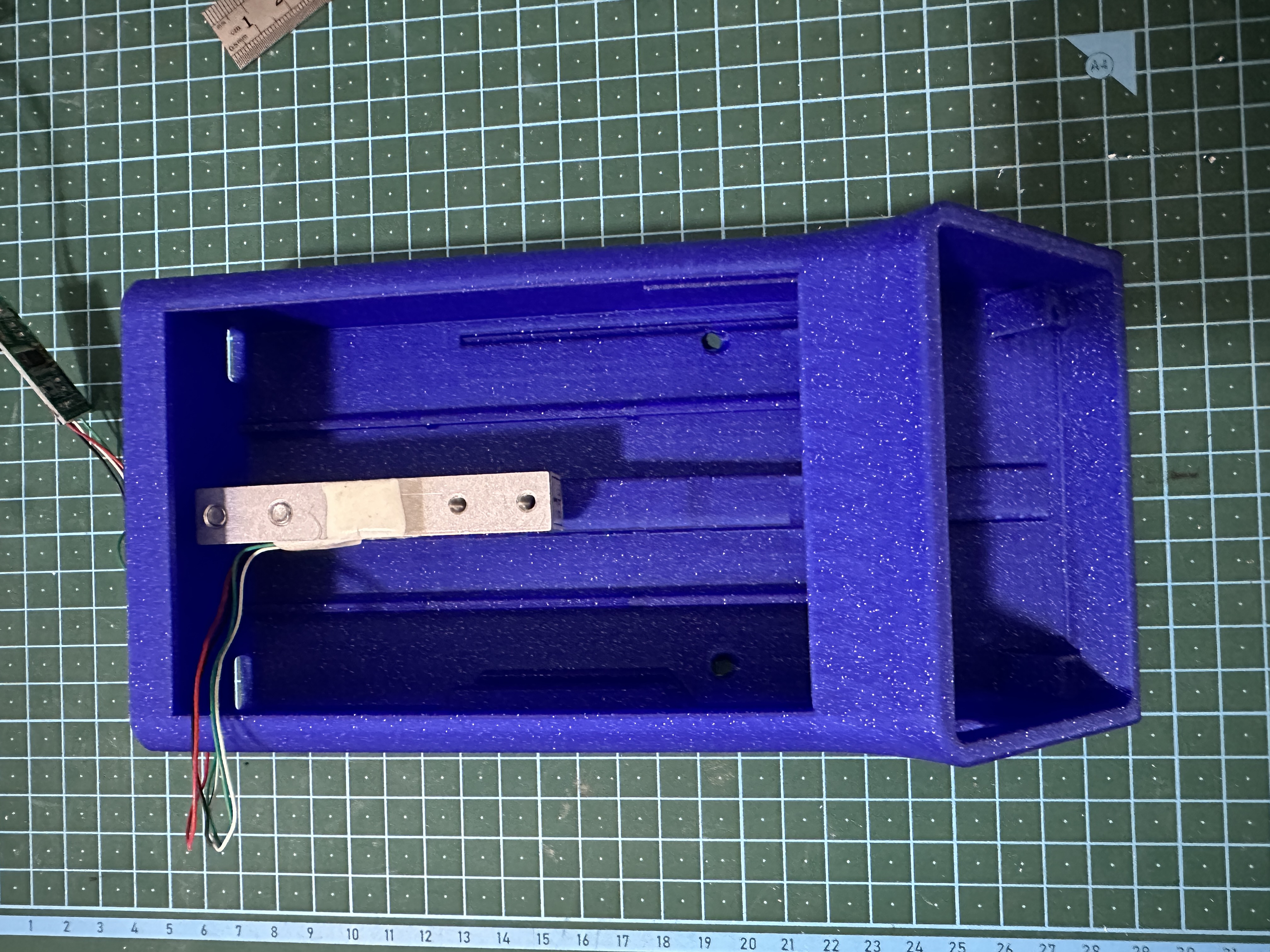
- Attach the load cell to the base using the two M5x30 screws.
- Position the load cell so that the wires come out to the left.
- Insert screws from the bottom of the base.
- Tighten firmly to prevent any vertical movement of the load cell.
- Make sure the load cell ends up centered inside the box.
Load cell bottom screws
Load cell mounted
Mount the HX711
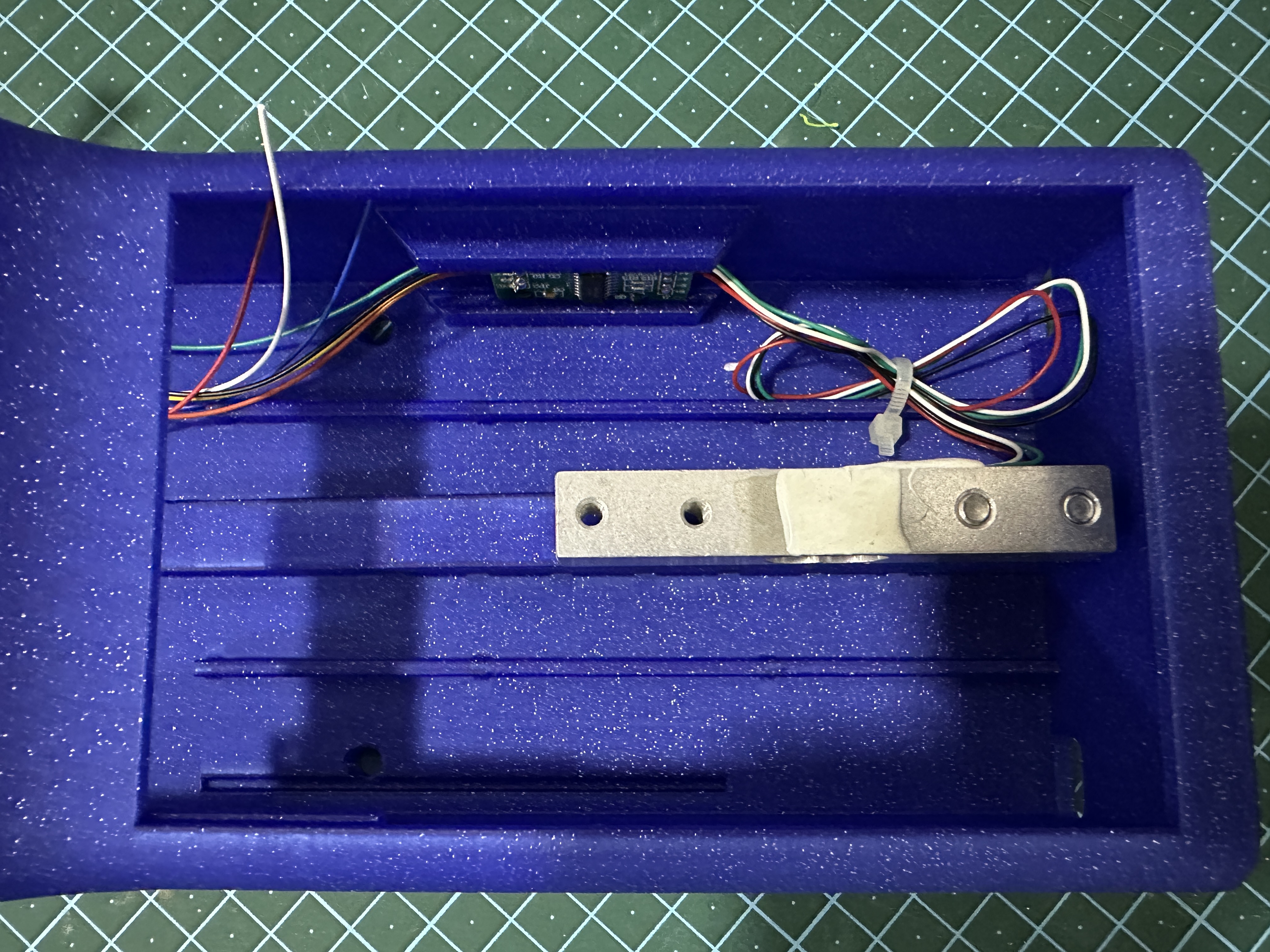
- Slide the HX711 into the rails on the left side of the case.
Mount the PN532
- Slide the PN532 into the rails on the right side of the case, with the antenna facing outward.
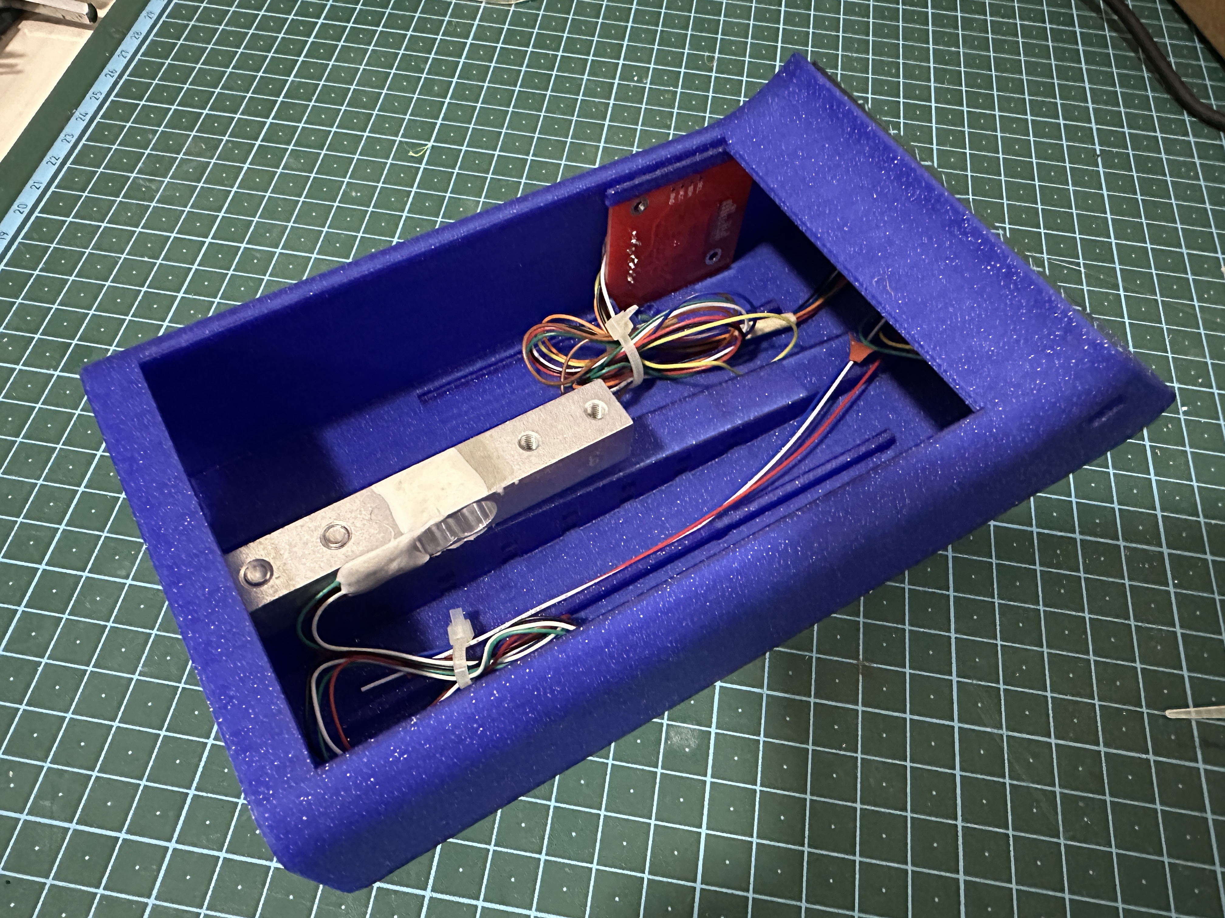
WT32-SC01-Plus (Display) Installation
- Format the SD card using the classic FAT file system. You can do this directly with your Bambulab printer. If formatting on a computer, ensure you select the original FAT format, not any of the newer variants introduced over the years.
Windows may have issues formatting SD cards with FAT for use with SpoolEase, especially when using third-party tools on large cards.
If you encounter errors in SpoolEase related to storing or accessing files right after setup, use a Bambu Lab printer to format the SD card, as this method is known to work reliably.
- Insert the microSD card into the slot in the WT32-SC01-Plus just below the USB connector. You should feel it click into place. To remove it, press it again and it will pop out.
Connect the boards
- Connect the PN532 to the 8 pin connector on the WT32-SC01-Plus
- Connect the HX711 to the 7 pin connector on the WT32-SC01-Plus
- Place the WT32-SC01-Plus in position.
You can mount the M2 screws from the bottom holes but do that only if it is loose.
Make sure not to push the screws too much as it may break the display!
- Arrange the wires to avoid interfering with the PN532 antenna or the WT32-SC01-Plus board (to minimize Wi-Fi interference).
- Make sure the wires do not interfere with the load cell or the top plate covering the case, as this can affect the spool weight readings.
- Use the mounting points in the case to secure the wires with zip ties.
- Fit the USB cable into the slot of the WT32-SC01-Plus. Depending on the stiffness of your cable, it may be tricky due to the board design. If it’s difficult to connect while the board is in place, try connecting the cable before placing the board.
Install the Plate
Once everything is mounted and the wires are secured, place the curved top plate over the case as its cover. Note the plate is directional - the flat side should be on the back of the case. Make sure no wires are pinched or interfere with the plate, not even lightly, then secure the plate with M4x20 screws.
If you're reusing your existing scale components, note that its M4x30 screws are not compatible with the Duo. They will come into contact with the case beneath the load cell and push it upward.
Congratulations! Build is Done
You are the proud owner of SpoolEase Duo
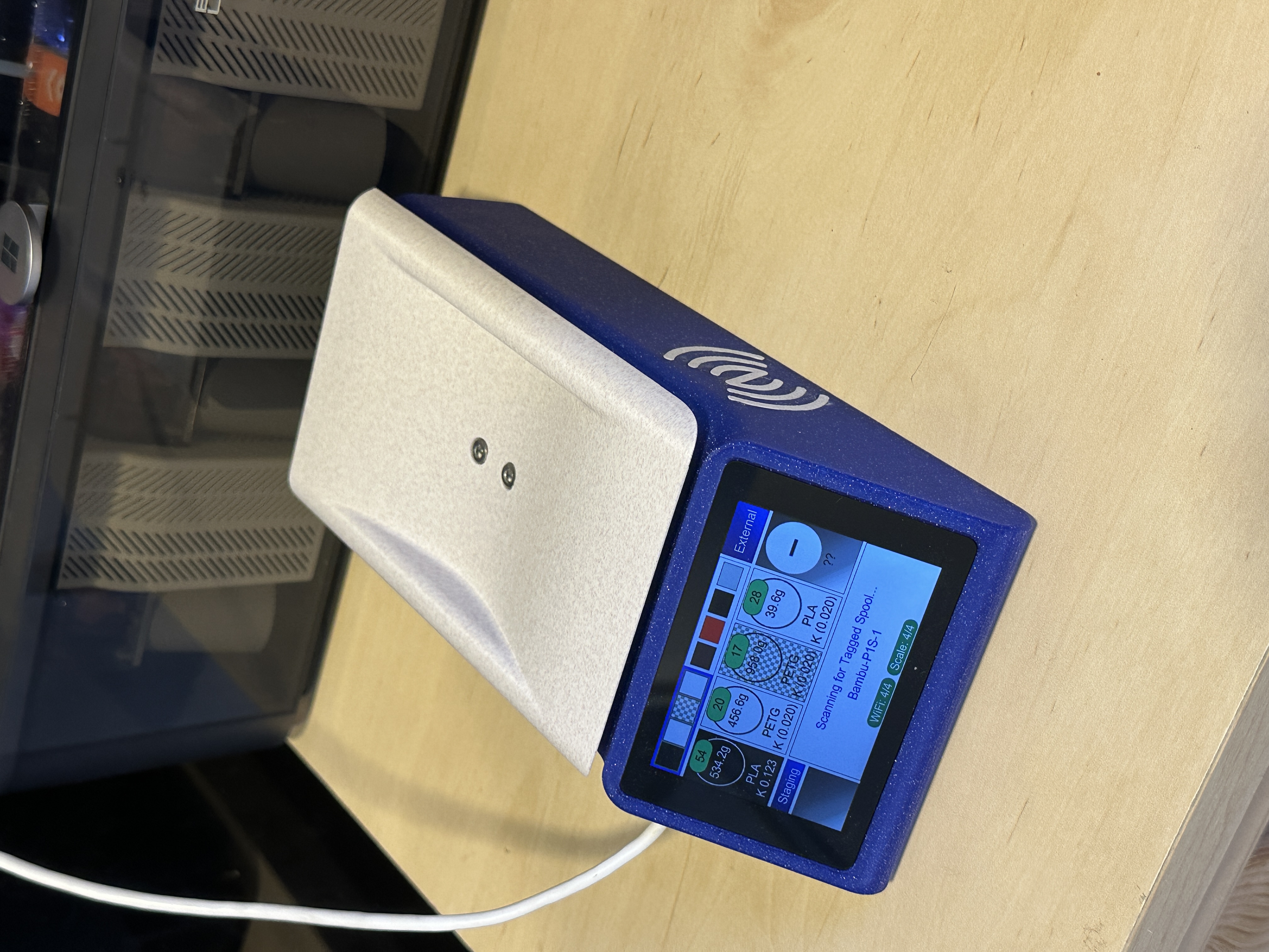
Setup
Follow the Duo Setup Guide to set up the device and enable its local scale.
Calibrating the Scale
To ensure accurate weight measurements, you must calibrate the system to your specific load cell. This calibration needs to be performed only once after completing the case assembly, or whenever you suspect the accuracy has drifted.
If you have both a local and a remote scale, select the correct scale page before calibrating. Calibrate each scale separately.
Follow these steps to calibrate:
- Find an object weighing approximately 750g - 1kg and measure its exact weight on a trusted scale.
- On SpoolEase Duo, go to the settings screen by swiping up from the bottom of the screen.
- On page 2, press "Calibrate Scale".
- Place the scale on a steady surface with nothing on it to establish the zero point.
- Press the "Tare" button.
- Place the calibration object on the scale and wait a few seconds for the weight measurement to stabilize.
- Enter the object's exact weight in grams using the keypad on SpoolEase Duo and press "Ok". The dialog will close.
- Return to the main screen and verify the object's weight appears accurately (within ±1g tolerance).
Optional Build Enhancements
- Easier USB-C access: Use a USB-C extension cable to make the port on the left side easier to reach. The WT32-SC01-Plus board's design places the port slightly recessed inside the case.
- Power from the back: Use a 90-degree USB-C adapter to route the power cable through the back of the case.
- Removable wiring: Solder Dupont pins or other connectors to the boards instead of soldering wires directly to them. This allows the wires to be disconnected when needed.